To control an individual LED, you set its column LOW and its row HIGH. To control multiple LEDs in a row, you set the row HIGH, then take the column high, then set the columns LOW or HIGH as appropriate; a LOW column will turn the corresponding LED ON, and a HIGH column will turn it off.
Tip - Pins set to OUTPUT by use of the PinMode command are set to LOW if not otherwise stated
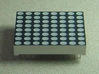
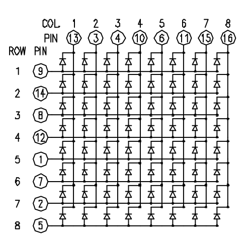
Although there are pre-made LED matrices, you can also make your own matrix from 64 LEDs, using the schematic as shown above.
It doesn’t matter which pins of the microcontroller you connect the rows and columns to, because you can assign things in software. Connected the pins in a way that makes wiring easiest. A typical layout is shown below.
Here's a matrix of the pin connections, based on the diagram above:
Matrix pin no.
|
Row
|
Column
|
Arduino pin number
|
1
|
5
|
-
|
13
|
2
|
7
|
-
|
12
|
3
|
-
|
2
|
11
|
4
|
-
|
3
|
10
|
5
|
8
|
-
|
16 (analog pin 2)
|
6
|
-
|
5
|
17 (analog pin 3)
|
7
|
6
|
-
|
18 (analog pin 4)
|
8
|
3
|
-
|
19 (analog pin 5)
|
9
|
1
|
-
|
2
|
10
|
-
|
4
|
3
|
11
|
-
|
6
|
4
|
12
|
4
|
-
|
5
|
13
|
-
|
1
|
6
|
14
|
2
|
-
|
7
|
15
|
-
|
7
|
8
|
16
|
-
|
8
|
9
|
Step 1: What You Need?
1 x Arduino Board ( Arduino UNO R3 used in this tutorial.)
1 x 8x8 LED Matrix
2 x Potentiometer (10k Ohm)
1 x Breadboard
1 x USB Type-B Cable
Female-to-Male Jumper Wires
Optional
Don't have components? Don't worry. Just click the component's name. 1 x 8x8 LED Matrix
2 x Potentiometer (10k Ohm)
1 x Breadboard
1 x USB Type-B Cable
Female-to-Male Jumper Wires
Optional
Step 2: Build Your Circuit.
The 16 pins of the matrix are hooked up to 16 pins of the Arduino board. Four of the analog pins are used as digital inputs 16 through 19. The order of the pins is assigned in two arrays in the code.Two potentiometers, connected to analog pins 0 and 1, control the movement of a lit LED in the matrix.


Step 3: Upload The Code.
1. Select the Arduino board type: Select Tools >> Board >> Select your correct Arduino board used.
2. Find the port number by accessing device manager on Windows. See the section Port (COM&LPT) and look for an open port named "Arduino Uno (COMxx)". If you are using a different board, you will find a name accordingly. What matters is the xx in COMxx part. In my case, it's COM3. So my port number is 3.
Select the right port: Tools >> Port >> Select the port number.

3. You can find this code in the example of Arduino IDE.
Select File >> Examples >> 07. Display >> RowColumnScanning
Click press the "upload" button (see the button with right arrow mark).
Download:
Arduino IDE
My Robot Education Sdn. Bhd. (Robotedu.my) was founded in 2015 as the first robotics education centre in Malaysia to provide Arduino-based robotics courses for youths. Our vision is to be able to provide robotics education to every youth in Malaysia.


0 comments:
Post a Comment